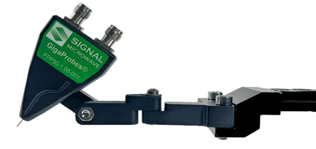
DVT-FPPNN High Fidelity Two Probe Kit
40/50/70/110 GHz Wide Pitch True Differential TDR/VNA Probes
.png)
.png)

Enlarged side view of probe tips
Part Numbers
- DVT-FPP40, DC-40 GHz Differential Probe
- DVT-FPP50, DC-50 GHz Differential Probe
- DVT-FPP67, DC-70 GHz Differential Probe
- DVT-FPP110, DC-110 GHz Differential Probe
US Patents 10852322, 11175311 (Other pats pend)
Electrical Characteristics
- Differential Probe Connectors/Frequency
- Ranges: 40 GHz /2.92 mm, 50 GHz /2.4 mm, 70 GHz/1.85 mm and 110 GHz/1.0 mm
- Linear Roll-off Frequency Response
- Tightly Coupled Fully Balanced Differential Probes
- No Ground Contact Probe Tips
- Measures: True Differential S-parameters
- 100 Ohm (nominal) Differential Impedance
Mechanical Characteristics
- Differential controlled-impedance PCB-Based Design
- Fixed Pitches: 1 mm (1000 um), .8 mm (800 um), .6 mm (600 um), to 0.35 with offset probing
- A .6 mm probe can cover 0.35 to 1 mm test pad pitches.
- Rugged Flex-Steel beryllium Probe Tips
- Fixed Pitch Signal-to-Signal Probe Tips
- No Ground Pin Required
- Included 2-Axis Adapters used for mounting Probe Positioners (+/- 90 °)
Probe De-Embedding
- Probe de-embedding files are included
- Each de-embedding file has the serial number of the associated probe
Service and Support
- Industry’s Only 1 Year Unconditional Warranty
- Replacement Repair Service
Instrument Compatibility
TDR, VNA and BERT Scope Instruments
Applications
- Measuring Final PCB Prototype Designs against specs
- Differential impedance, S-Parameter bandwidth wide-pitch measurements up to 110 GHz
- 90 GHz Nyquist S-parameter Analysis of PAM6 Designs at 448 Gbps


Raw bandwidth specs for the 40 to 110 GHz differential probes. These SDD21/11 differential probe bandwidth plots are generated using actual “thru” measurements with the Signal–Signal probe tips set to 1 mm and no de-embedding applied (110 GHz probe tested at .8 mm pitch).
Architecture Comparison
True Differential PCB-Based vs. Wire-Based SS Probe Probe architecture directly affects differential SI measurement accuracy
Wire-Based SS Probes
- Datasheet: SS differential probe, 50 ± 2 Ω input
- Architecture: Two separate internal conductors with internal ground/shield reference
- Electrical behavior: Two 50 Ω single-ended paths
- Not a true 100 Ω balanced differential structure
- Time domain: poor to significant mismatch impedance reflections at probe tips
- Frequency domain: Insertion-loss contains standing wave ripple which lowers return loss (~4dB) measurements
- VNA Measurements: Odd-mode S-Parameters
- Probe de-embedding file: Often not included, requiring additional software, a 2xThru board, and extra customer time to create them.
- Probe tips: fixed pitch, one probe may be required for each unique test pad pitch, increasing cost and setup time, no warranty

DVT-FPPNN PCB-Based SS Probes
- Datasheet: True differential 94 Ω input impedance
- Architecture: Tightly coupled, fully balanced internal PCB differential trace
- Electrical behavior: One controlled true differential transmission structure
- Time domain: No mismatch Impedance reflections
- Frequency domain: Linear insertion loss, no standing wave ripple, High return loss (-10dB/-17dB)
- VNA Measurements: Odd mode S-Parameters
- Probe de-embedding file: Included with probe, no extra software required
- Unique probe tips design: Flex Steel, 1 Yr unconditional warranty, one 0.6 mm DVT-FPPNN probe can contact >10 differential test pad pitches from 0.35 mm to 1.0 mm for complete prototype PCB characterization without multiple fixed-pitch probes.
PCB-based probes
−10dB/-17 dB return loss (typical of DVT-FPPNN probes) corresponds to ~98% power delivered (~2% reflected), indicating very high transmission efficiency.
Wire-based probes
−4 to −5 dB return loss corresponds to ~60–68% power delivered (~32–40% reflected energy), resulting in significantly reduced measurementfidelity compared to higher-return-loss PCB-based probes.
A wire-based SS probe can measure differential signals, but a PCB-Based DVT-FPPNN probe is designed
to preserve differential signal fidelity.

Differential Probe Architectures
PCB-Based Probes vs Wire-Based Probes
Impact of Probe Design on S-Parameter Measurement
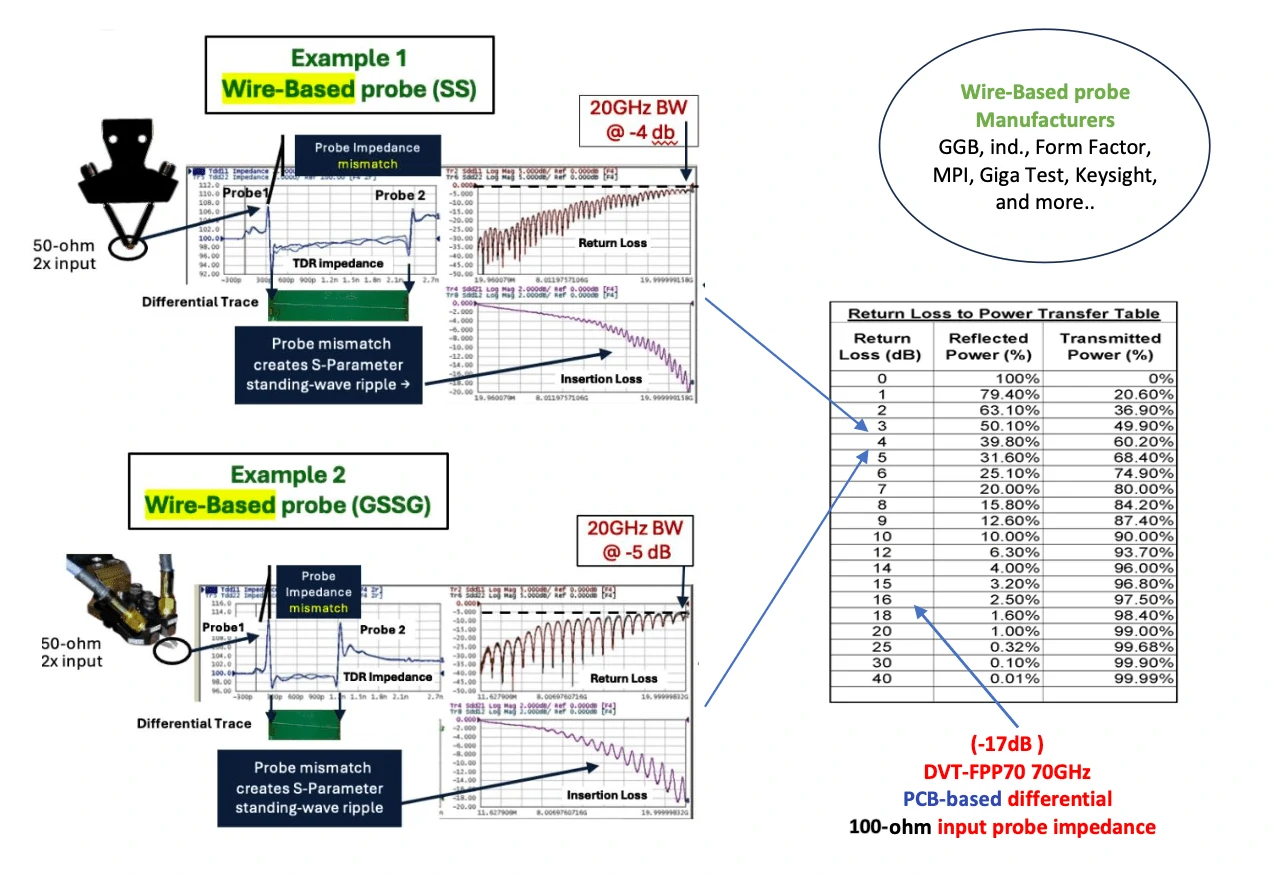
DVT-FPPNN PCB-Based probes reveals more of the DUT’s True Signal Integrity Performance
Building a Desktop Dual Time & Frequency Domain Measurement System
To configure a dual desktop probe system:
- Connect two DVT-FPPNN probes to the end of the probe arm of each DVT-FP250 Probe Positioner.
- Depending on the size of the board, use one or two DVT-CS-3 or DVT-CS-1 cameras to verify the probes contacting the probe pads (as small as <20 mils in diameter) and to planarize the probe tips to the test pads. Each USB camera probe image is displayed using its utility software on a PC display to verify that both probes are making contact at the same time. Using two cameras vastly reduces setup times compared to using one camera and repositioning the camera each time you move the probes to a different probing location.
- For horizontal probing, use four DVT-SM Holders to secure the corners of your PCB to keep it from moving while probing. You can also remove a segment from two of the holders and place them under the PCB near where it will be probed to keep the board from bowing (At least 6 holders recommended).
For vertical probing, contact us for custom configurations.
Probe System Components
DVT-FPP67 70 GHz Differential Dual Probe Kit
.png)
70 GHz Dual Probe Differential TDR and S-Parameters Probe kit. Contains two fixed differential probes. Includes a copper shorting block for creating probe models.
DVT-FP250 Probe Positioner

Rigid arm probe manipulator with XYZ pitch 40 TPI controls & magnetic base. Recommended for probing with DVT40 and DVT-FPPXX probes.
DVT-CS-1 Camera System
.png)
The Camera System is used for the accurate placement of probe tips on the test pads, probe tip planarization and calibration.
DVT-FP100 Magnetic Bases
.png)
DVT-FP100-1IN, DVT-FP100-1.5IN and DVT-FP100-2IN Stackable 1", 1.5" and 2" magnetic blocks used to raise the probe and camera positioners to clear the test board.
DVT-PB100-24 Probe Bridge
.png)
A Versatile bridge with magnetic base for probing applications which extends the probe reach to enable probing of larger boards.
2-Axis Probe Adapter
This adapter, for the DVT-FPPNN probes only, improves ease and efficiency in probing vertical and horizontal PCBs on tight-pitched test pads and when complex angles are required.
DVT-SM Holders
.png)
Stackable Magnetic PCB Holders on the corners of a PCB keep it from moving while probing. Also, remove a segment from two holders placing them under the PCB near where it will be probed to keep the board from bowing (6+ holders recommended).