S-Probe SP-GR 30/20 GHz Series
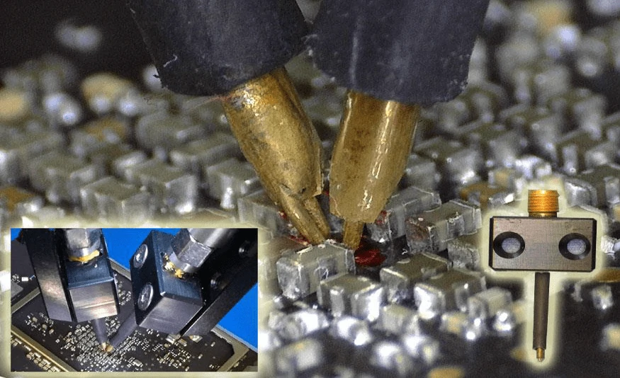
Rugged, Single-Ended 30/20 GHz Probe Capable of Probing on Uneven Solder Bumps
Features
- High Bandwidth: DC to 30/20 GHz
- Low Insertion Loss: < 3 dB @ 30 GHz for probe pitch ≤ 0.5 mm
- High Repeatability: No moving parts
- Strong beryllium copper (BeCu) tips: perfect for direct probing of uneven surfaces, such as solder pads & components.
- Probe-tip Calibration: accurate measurements without the need of soldering semi-rigid RF cables
S-Probe series is designed for RF, signal integrity, and power integrity testing of printed-circuit boards. Microprobes are not suitable for this type of measurements due to their fragility. Constant shrinking size of circuit components makes soldering semi-rigid RF cables to test gigahertz circuits impractical. The rugged S-Probe and its calibration substrate (TCS70) allow engineers to perform probe-tip calibration for accurate, repetitive measurements.
Specifications
- Bandwidth: 30/20 GHz (0.25/0.4/0.5 mm pitch) 18 GHz (0.8/1.0 mm pitch) 16 GHz (1.2/1.4/1.6 mm pitch)
- Insertion Loss: Less than 3 dB @ bandwidth
- Impedance: 50±2 Ohm
- Connector Type: Female 2.92mm/30GHz, SMA/20GHz
- Size/Weight: 38x20 x12 mm (1.5x0.8x0.5”) / 8 gm
- Probe Force: 30 gm (typical) 100 gm (max w/o damage)


20 GHz PART NO. | BW (GHz) | PITCH |
SP-GR-2015025 | 20 GHz | 0.25 mm / 10 mil |
SP-GR-201504 | 20 GHz | 0.4 mm / 16 mil |
SP-GR-201505 | 20 GHz | 0.5 mm / 20 mil |
SP-GR-181508 | 18 GHz | 0.8 mm / 32 mil |
SP-GR-181510 | 18 GHz | 1.0 mm / 40 mil |
SP-GR-161512 | 16 GHz | 1.2 mm / 48 mil |
SP-GR-161514 | 16 GHz | 1.4 mm / 56 mil |
SP-GR-161516 | 16 GHz | 1.6 mm / 64 mil |
30 GHz PART NO. | BW (GHz) | PITCH |
SP-GR-3015025 | 30 GHz | 0.25 mm / 10 mil |
SP-GR-301504 | 30 GHz | 0.4 mm / 16 mil |
SP-GR-301505 | 30 GHz | 0.5 mm / 20 mil |
PROBE PITCH VS. COMPONENT SIZE
PROBE PART NO. | SIZE |
SP-GR-2015025 | 01005 |
SP-GR-201505 | 0201 |
SP-GR-181510 | 0402 |
SP-GR-161514 | 0603 |
Measurements
RF Measurement
The following S21 measurement of a TDK 2.45 GHz low pass filter (P/N: DEA102500LT- 6307A1, Size 0402) shows that S-Probe performance is better than that of soldering a coaxial cable.

TCS70 Calibration Substrate
S-Probe product family includes a TCS70 calibration substrate with short, open, load, and thru (SOLT) standards for S-parameter calibrations. This substrate enables a user to move the measurement reference point directly to the probe tips for accurate, repetitive testing.

Specifications
SOLT Standards: Open, short, thru, and 50 Ω
Frequency: 30 GHz
Probe Pitch: 0.2 mm – 1.0 mm
Substrate: Polished aluminaContact Material: Gold Accuracy: < 0.5% (25 Ω, 50 Ω) Size/Weight: 17.3 x 9.4 x 0.6 mm (0.68 x 0.37 x 0.025 in) / 1 gm
2-Port Probe-Tip Calibration
Probe-tip calibration allows accurate, repetitive S- Parameter measurements.


Recommended Accessories
• DVT-FP250 (xyzθ) Precision Positioner
• DVT-FP100 (xyzθ) Precision Positioner
• DVT-SM Holder• DVT-FP80• Dino-Lite Digital Microscope

S-probe on DVT-FP250

Dino-Lite Microscope

Typical Probing Setup